Birdman1 goes DISCOVERY PRO- TEAM BLACK SHEEP
just started photo blogging, so this build is in full workflow as we speak, forgive me for now , this blog will change from hour to hour in the next coming days! thx for your understanding
The link list
TBS DISCOVERY PRO: http://team-blacksheep.com/products/prod:discopro
TBS ESC-MOTOR SET: http://team-blacksheep.com/products/prod:900kv_30aesc
TBS instruction/ hint page: TBS DISCOVERY PRO Installation Notes
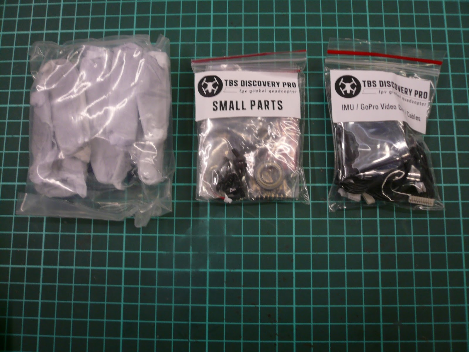
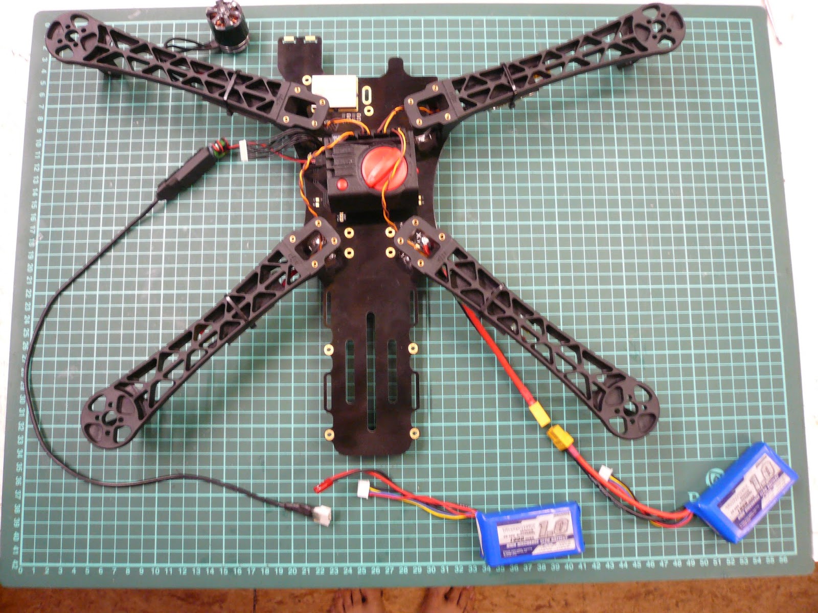
the content of a TBS DISCOVERY PRO kit


My shopping list!


let's start building!
I start with the esc! standard layout

the Esc need some work before i gonna use them,
they are good but lets make them perfect!
and as you all know, no pain, no gain!!
they are good but lets make them perfect!
and as you all know, no pain, no gain!!


PICK YOUR COLOUR!

Mount 1 arm in the front and 1 in the back, now a extra note concerning the screws delivered with the package( sorry TBS) they are already way better then those delivered with the
STANDARD TBS DISCOVERY
but
they still are far off from the quality screws from DJI !
they fit ,okay, but there is a lot of play,
they are good for spots that you only access once. If you have some DJI screws laying around then use those in the final stage!!
STANDARD TBS DISCOVERY
but
they still are far off from the quality screws from DJI !
they fit ,okay, but there is a lot of play,
they are good for spots that you only access once. If you have some DJI screws laying around then use those in the final stage!!

Fix the esc like you would for real

fix 1 motor to the arm

check the wiring and how it will come in the (hopefully ) nearby future.


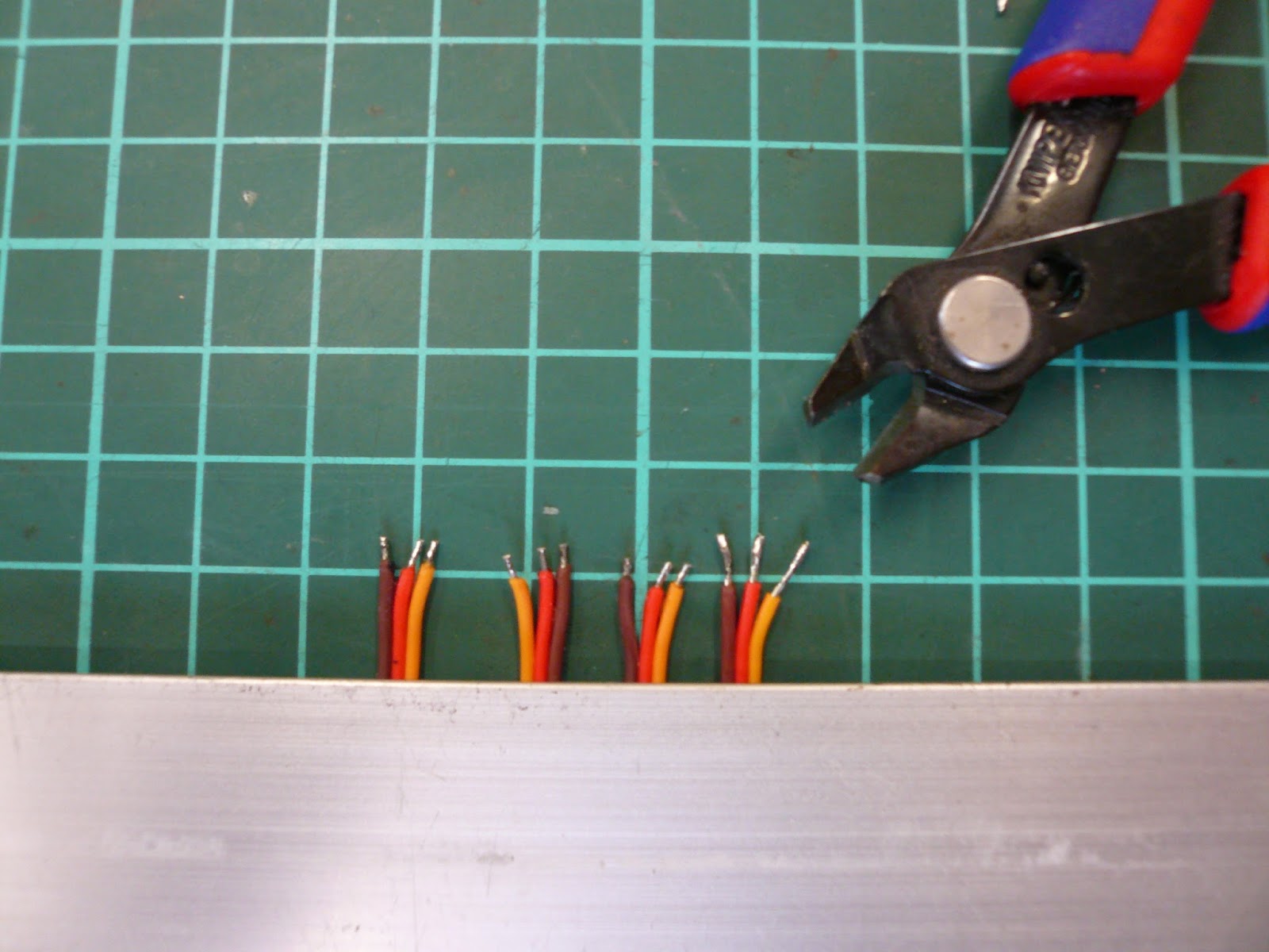
cut the servo wire ( jep really!!)


Cut the wiring to the correct lenght

Do the same with the servo cable


Repeat for the back


This is what you get,

Now make sure that you get a copy from each lenght

MY SOLDER TOOLS

solder the tips before you connect them to the print, then cut them to the correct lenght!

remove the old servo cable

and the brushless motor connection

remove the red / positive wire from the servo cable

solder them to the print! make sure that you make the correct connection (black on the side from black)

now solder back the brushless motor connection

now I was lucky, in checking all my connections I came to one that had a cold solder connection from UH, hmmmm.......
so make sure that you check yours ( by the way, I do this always)

it's clear what the cause is...... I was VERY lucky!!!!


PROTECT THE SOLDERPADS WITH LIQUID TAPE
aka PLASTIDIP
aka PLASTIDIP


New transparant crimpsock! FINALLY
they are now ready to be soldered to the
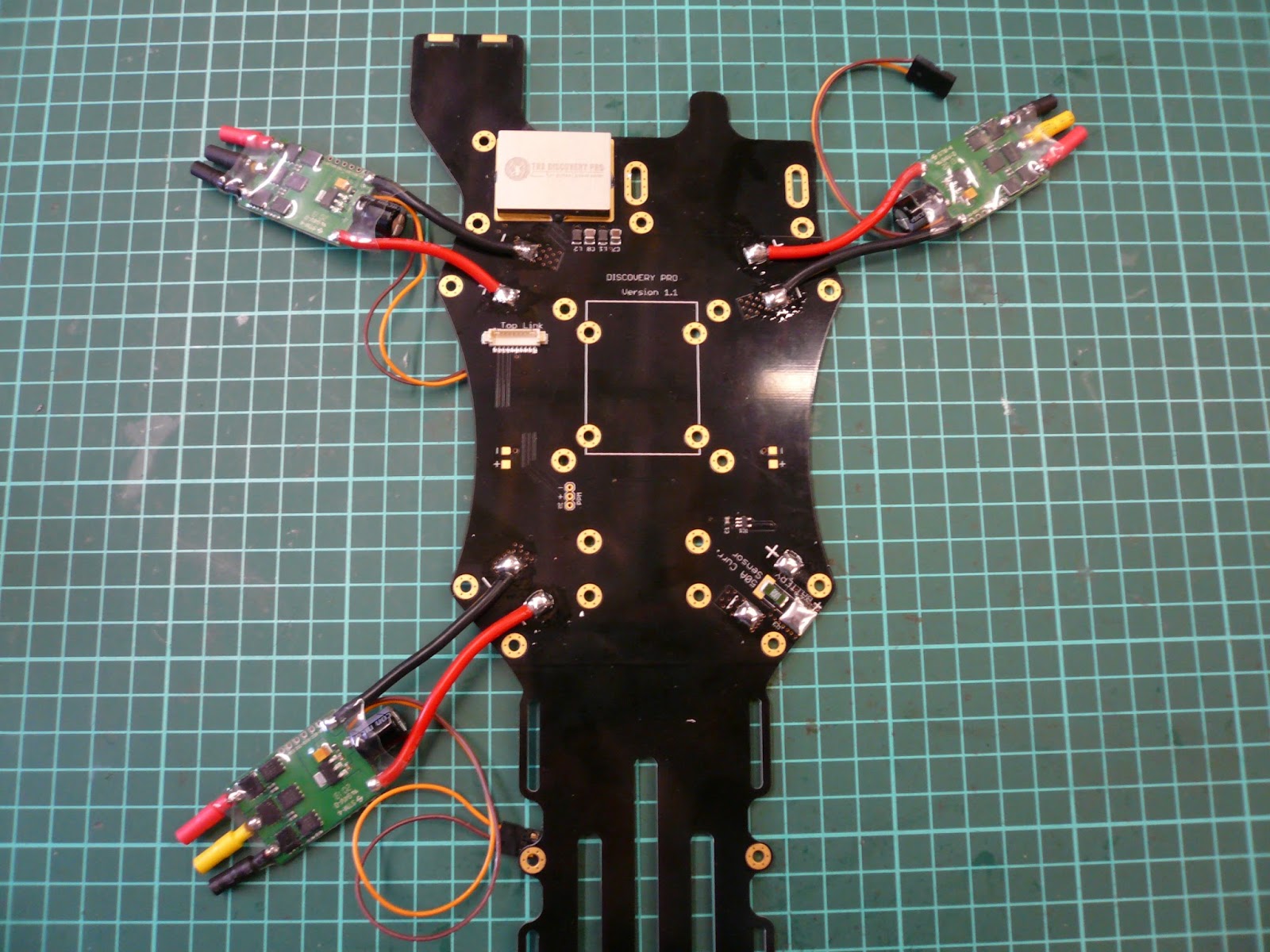
TBS DISCOVERY PRO FRAME
TBS DISCOVERY PRO FRAME

LAYOUT


FIRST BRING SOME TIN TO EACH SOLDERPAD

ATTENTION, MAKE SURE THAT YOU SOLDER THE WIRE'S INCLINATED INWARD's, why? later on you will be screwing those DJI arm's to the frame, if you solder straight forward your arm will push on those wire's, like that you have enough clearence!

number one

two

three
four, neeehn !!! Gotcha lol , first the powerconnection!!

four


Okay, I go for black

so I used dji screws for the obvious reason

this is a piece of neopreen 4mm thick

made 4 pieces from 5cm

this goes between the esc and the DJI arm, 2 advantages- anti slip and vibration absorber-
1 disadvantage- heat dissipation is less


nice and neat!!

connection cable between lower and upper plate

make sure that it is completely till the end

Preparation on the upper plate


NAZA V2 arrived


connect the esc's (all of them) and set tester to maximum

connect power to tester


now, to be clear, I will be using the PPM SETUP WITH EZUHF
BUT
A LOT OF PEOPLE ASK ME ABOUT THE TRADITIONAL SETUP
SO HEREBY A BIG HINT TO CUT DOWN ON THE CABLE BOOM
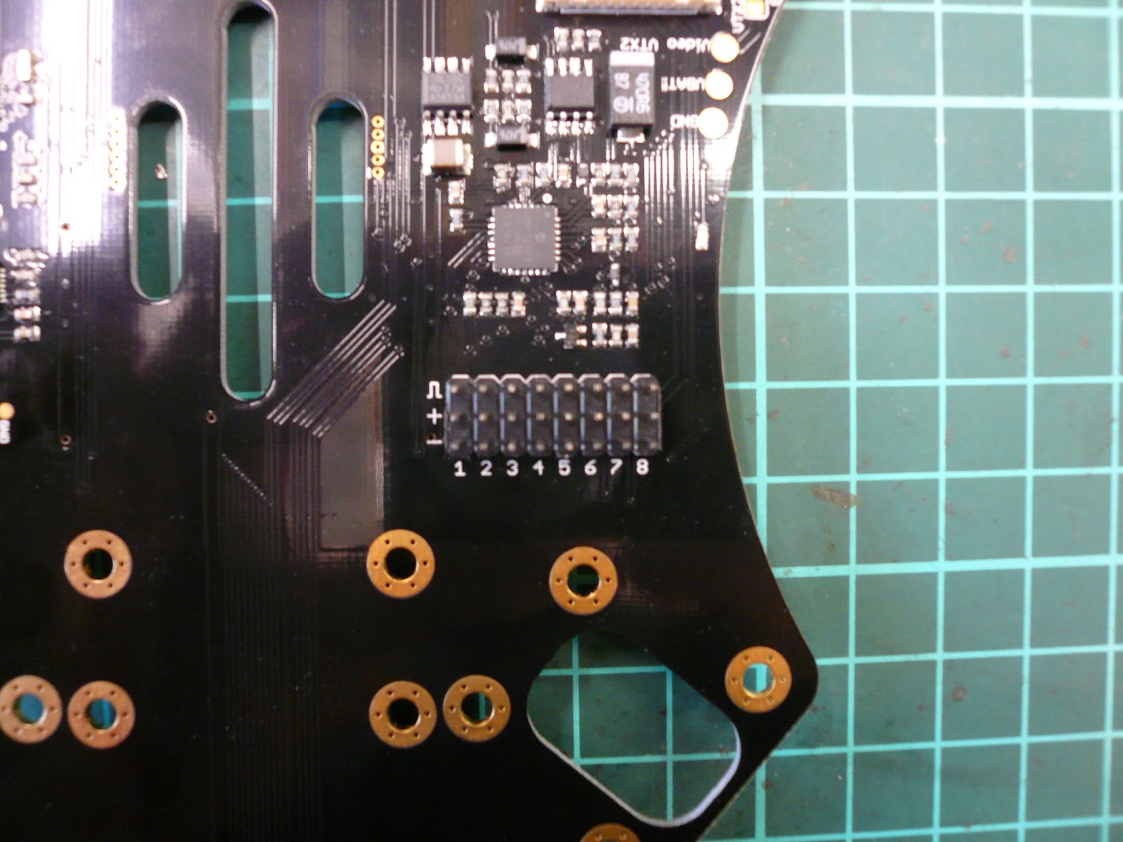
Connection diagram for traditional receivers
A E T R U X1 X2 X3 STANDS FOR THE NAZA MODULE
1 2 3 4 5 6 7 8 IS FOR THE CONNECTION TO THE UPPERPLATE AND THATS ALSO HOW IT RUNS TO THE BACK


copy it now to the module
attention: signal = bottom from the module


orange to the outside


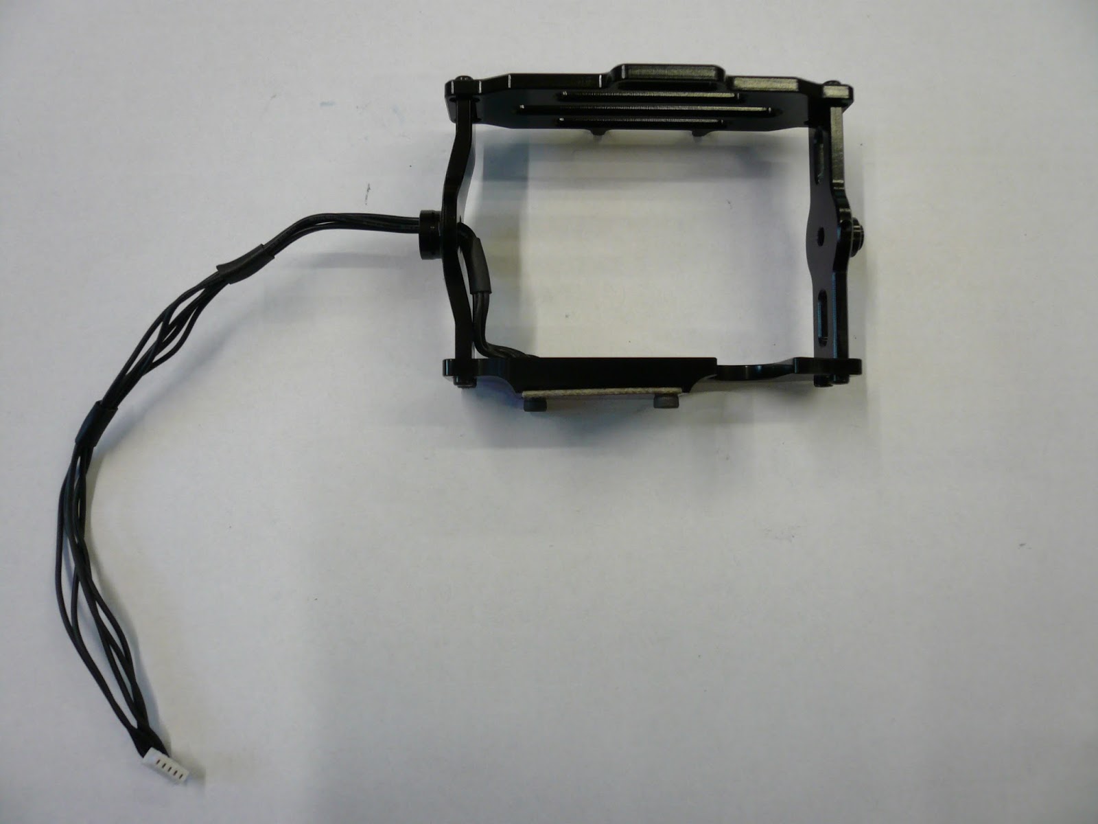
TBS DISCOVERY PRO BRUSHLESS GIMBALL ASSEMBLY


parts revealed

extra necessary parts

ATTENTION- concerning the use of loctite- All thought the gimball is a close as it can get to be ready it still needs some tweaking and tuning. in fact , you can use the gopro2 and gopro3 but you have to decide upfront which one it will be,
afterall the complete gimball is based and 360° balance.
SO ONLY USE LOCTITE WHERE I SHOW THE BOTTLE.
Later on you can put loctite when everything works flawlessly
Just unscrew one screw at the time, add the loctite, and put it back.
first step

front and back plate

make sure that you attach both in the correct direction


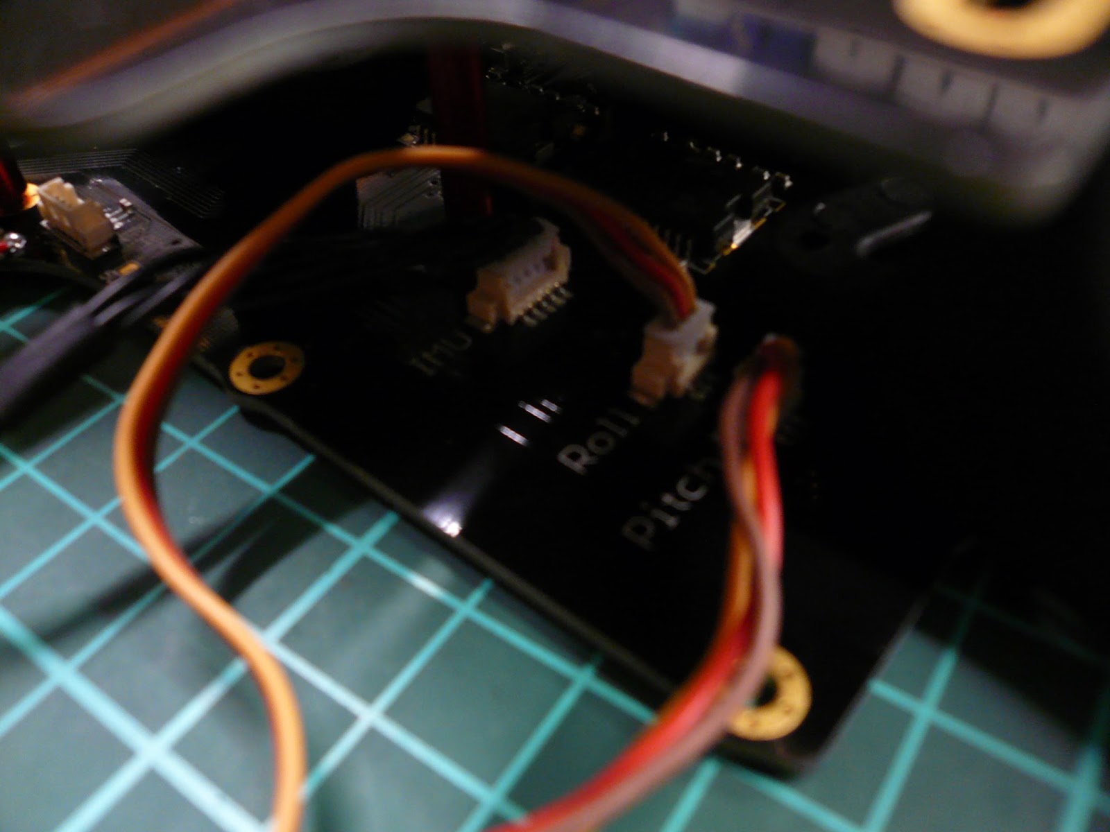
micromolex cable with 5 connections

plug it in the IMU, it's not easy, do it gentle!


guide the cable through the hole and bolt the IMU to the upperplate

this is how the casing goes together


fix the right arm( flat side inwards)

fix the left side ( again flat side inwards)


IMU PLATE goes on top


fold the micromolex cable as small as possible

guide it through the cnterhol from the left side

guide the bearing over the micromolex cable


put the 12mm screw in position


guide the arm over the cable and put it flat with the flange of the bearing, tie down the screw,
DO NOT OVERTIGHTEN!
DO NOT OVERTIGHTEN!

make 100% sure that the cable moves free, no rubbing or what so ever, then guide it through the hole from the arm and give it some play

fix the backplate to the left arm (the cable needs to go through the U hole

fix the right arm


pictures in hold

